
In a standard pool, the filtration system is largely independent of the pool structure. Skimmers, bottom drain, pump and filter can be specified and connected without the hydraulic layout having any significant impact on the visual result.
In an overflow or infinity pool, this is not the case. The water surface is the design – and its stability depends entirely on the precision of the hydraulic circuit. The filtration system is not added after the pool is designed. It is part of the design from the outset.
For the hydraulic and filtration drawings we produce for overflow and infinity pool projects, see our pool hydraulics & filtration design page.
How the hydraulic circuit differs in an overflow pool
In a skimmer pool, surface water is collected through skimmers set into the pool wall. Return inlets are positioned just below the water surface – this creates a current that pushes floating debris and impurities towards the skimmers, where they are drawn into the filtration circuit.
In an overflow pool, the water surface spills continuously over the overflow channel and flows by gravity into the balance tank. The pump draws water from the balance tank and pushes it through the filter and back into the pool. Return inlets are positioned at the floor of the pool rather than near the surface. The surface is already in constant movement towards the overflow channel – floor returns create an upward circulation that distributes treated water evenly throughout the full water column.
The balance tank is not a passive reservoir. It absorbs the variation in water volume caused by bather displacement, rainfall and thermal expansion, and it feeds the filtration pumps under controlled conditions. Its sizing, its position relative to the pool, and the pipe connections between the overflow channel, the tank and the plant room all need to be resolved at the design stage – before any concrete is poured.
The hydraulic layout within the pool shell
The position of each inlet, drain and return nozzle inside the pool shell is determined by the hydraulic plan. For overflow pools, this includes the overflow channel drains, the balance tank feed pipes, the floor return inlets and, where specified, the vacuum socket and any additional equipment connections.
Pipe diameter is not an aesthetic choice. It directly determines flow velocity, pressure losses across the circuit and the pump head required to maintain the design flow rate. Undersized pipes create turbulence and pressure imbalance – which in an overflow pool translates directly into an uneven water surface and a compromised visual effect.
Pipe routing also matters. Crossings and unnecessary elbows increase pressure losses and create stress points in the network. A well-planned layout minimises fittings, follows the shortest logical path from each pool fitting to the plant room, and separates the suction, return and overflow circuits clearly – both on paper and on site.
Once the slab is cast, none of this can be corrected without major structural intervention.
Plant room design and equipment sequencing
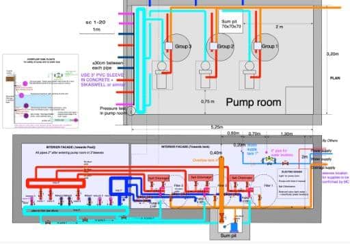
The plant room layout maps the complete filtration system – pump and filter positioning, pipe connections, valve sequencing, water treatment equipment, balance tank regulation and, where required, heat pump bypass and heating circuits.
In an overflow pool, the pump flow rate is determined by two parameters that must both be satisfied. The first is the pool volume – the water must complete a full turnover every four hours. The second, and often the more demanding, is the overflow edge length – the flow rate must be sufficient to maintain a continuous and even sheet of water across its full length.
In some cases, a pool with a small volume but a long overflow edge requires a flow rate that exceeds what is needed for the four-hour turnover alone. When these two requirements cannot be met by a single pump, a dedicated second pump is specified alongside the filtration pump – its sole function is to supply the additional flow required by the overflow edge. This is standard practice in overflow pool hydraulic design.
Equipment positioning follows the hydraulic sequence: from pool suction through pre-filtration, main filtration, treatment and heating, where applicable, to return. A plant room laid out in this logical order is faster to install, easier to maintain and simpler to diagnose when a fault occurs.
Key design parameters
Several parameters must be established before the hydraulic plan of an infinity pool can be produced.
Overflow pool volume, surface area, depth profile and overflow type determine pump and filter sizing, pipe diameters and the position of floor returns.
Balance tank volume is calculated primarily based on the pump flow rate, then adjusted based on pool volume. Bather displacement is negligible in practice – 10 swimmers displace less than 1 m³. What matters is the hydraulic reality of each project, not rules of thumb.
Plant room dimensions and access constraints affect equipment layout and maintenance access.
These parameters interact. A change in pool depth affects the volume, which affects the flow rate, which affects pipe diameters and pump selection. This is why the hydraulic design needs to be developed in parallel with the structural design – not after it.
Morana’s advice
A system that is right on the drawing can fail on site if the drawing is not followed.
Valve order, the fall of the pipes, and the position of the level sensors in the tank are easy to set from the drawing. They are hard to move once the plant room is finished.
Frequently asked questions: filtration system design
How is the pump flow rate calculated on an overflow pool?
The pump draws from the balancing tank and has to meet two conditions: the turnover required by the pool volume, and the flow needed to keep an even sheet of water along the full length of the overflow edge. When a single pump cannot cover both, a dedicated overflow pump is added.
How is the balancing tank sized?
Mainly from the water in transit: the film running over the edge and the water held in the gutter and pipes, all of which drains back into the tank when the pump stops. Bather displacement, rainfall and an operating reserve for the pump are then added. There is no standard size, as each pool has its own edge length and circuit.
When should the filtration system be designed?
Before the shell is built. Return inlets, main drains and gutter connections are cast into the structure, and none of them can be moved once the concrete has been poured. This is why the filtration drawing comes first.